The insatiable demand for bandwidth, driven by cloud computing, streaming video, and large-scale data analytics, has firmly established 100G networking as the new standard. However, as network architectures expand, the challenge is no longer just about achieving speed; it is about sustaining that speed over greater distances efficiently and cost-effectively. For network engineers and data center architects, selecting the right optical transceiver is a critical decision. Among the myriad of options, the QSFP-100G-ER4L-S module has emerged as a specialized solution. But what exactly is it, and how does it solve the complex problem of long-distance 100G connectivity?
This article provides a deep, technical analysis of the QSFP-100G-ER4L-S transceiver, aimed at optical module users who need to make informed procurement and design decisions. We will move beyond a superficial definition to explore its underlying technology, its precise application, and its crucial differences from other 100G standards. The goal is to clarify its unique value proposition, particularly for 40-kilometer applications, and determine if it truly is the optimal solution for your network’s extended-reach requirements.
The Evolving Landscape of 100G Connectivity

Before we can appreciate the specific role of an ER4L module, we must first understand the environment from which it emerged. The transition to 100Gbps was not a simple incremental upgrade. It represented a significant technological leap, particularly for the pluggable optics that form the physical layer of the network.
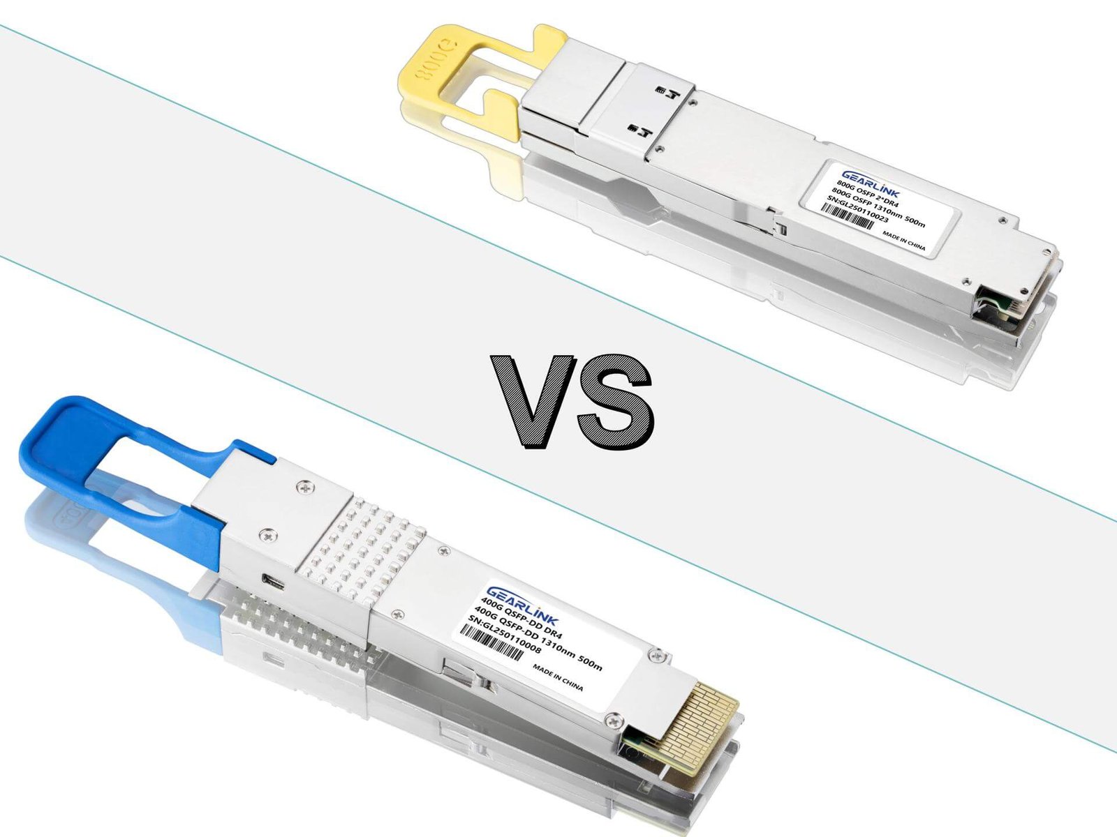
The Rise of the QSFP Form Factor
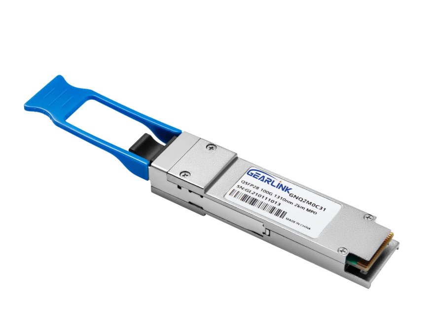
The Quad Small Form-factor Pluggable (QSFP) module has become the dominant form factor for high-speed data transmission, largely due to its density. By integrating four independent transmit and receive channels (hence “Quad”), the QSFP package—specifically the QSFP28 for 100G—could deliver 100Gbps (4x25G) in the same physical footprint previously used for much lower speeds. This high-density, hot-pluggable interface provides network operators with immense flexibility and scalability.
However, this compact size also presents significant engineering challenges. Inside this small module, manufacturers must accommodate complex lasers, drivers, receivers (photodiodes), and multiplexing/demultiplexing optics, all while managing power consumption and heat dissipation. This technological balancing act becomes exponentially more difficult as the target transmission distance increases from meters (inside the data center) to tens of kilometers (between data centers).
The Distance Problem: Beyond the Data Center Rack
The initial wave of 100G optics, such as 100G-SR4, was designed for short-reach applications (up to 100 meters) over multi-mode fiber. These are the workhorses within the data center. Soon after, 100G-LR4 modules addressed the 10-kilometer range, suitable for larger campus networks or connecting buildings in a metro area.
The problem arose when links needed to stretch further. Data Center Interconnect (DCI) applications, disaster recovery sites, and telecom aggregation points often require links of 20, 30, or even 40 kilometers. While coherent optics for 100G (and beyond) can cover hundreds of kilometers, they are often prohibitively expensive and power-hungry for these “medium-long-haul” 40km links. This created a critical gap in the market, a gap that standards like 100G-ER4 and, more specifically, 100G-ER4L, were designed to fill.
What Exactly Defines the QSFP-100G-ER4L-S Transceiver?
The name QSFP-100G-ER4L-S is not just a model number; it is a dense summary of the module’s capabilities. Understanding this name is the first step to understanding its function.
Deconstructing the Acronym
Let’s break down each component:
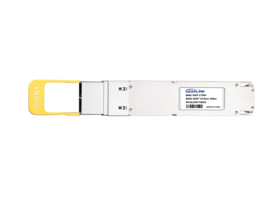
- QSFP: Quad Small Form-factor Pluggable. As discussed, this defines the physical module size and interface.
- 100G: The data rate, 100 Gigabits per second.
- ER4: This is the core optical specification. “ER” stands for Extended Reach, and “4” signifies four optical channels. This standard is designed to achieve a 40-kilometer link length.
- L: This single letter is arguably the most important differentiator. It stands for “Lite.” This indicates that it is a lower-cost, lower-power-consumption variant of the full 100G-ER4 specification.
- S: This suffix is often vendor-specific (like in the case of QSFP-100G-ER4L-S) and may denote a specific class, compatibility, or internal revision, but the defining technical standard is “ER4L.”
The “Lite” designation is not a marketing term; it has specific technical implications. A 100G-ER4L module is designed to be fully interoperable with a 100G-ER4 module on the receiving end. However, it achieves its cost and power savings by having a slightly reduced optical link budget. This trade-off is central to its design.
Core Technology: LAN-WDM Mux/Demux
To transmit 100Gbps over a single pair of single-mode fibers (one for transmit, one for receive), the QSFP-100G-ER4L-S employs a sophisticated technology known as Wavelength Division Multiplexing (WDM). Specifically, it uses the LAN-WDM wavelength grid.
Inside the transmitter, the 100G electrical signal (typically 4x25G NRZ) is used to drive four separate lasers, each operating at a different, precise wavelength (1295.56nm, 1300.05nm, 1304.58nm, and 1309.14nm). These four 25G optical signals are then combined (multiplexed) into a single fiber.
On the receiving end, a demultiplexer separates the combined optical signal back into its four individual wavelengths, which are then directed to four separate photodetectors.
This LAN-WDM technology is the foundation for all 100G LR4 and ER4 modules. The key challenge for 40km reach is maintaining the signal integrity and power of these four wavelengths over such a long distance.
The “Lite” Distinction and the Power of APD
To achieve a 40km reach, the receiver must be incredibly sensitive. Standard 10km LR4 modules typically use a PIN photodetector. In contrast, both ER4 and ER4L modules utilize an Avalanche Photodiode (APD). An APD provides an internal gain mechanism, essentially amplifying the weak optical signal that arrives after traveling 40km, much like a telescope gathers faint starlight. This APD-based receiver is critical for achieving the required link budget.
So, if both use APDs, what makes the “Lite” version different?
The primary difference lies in the optical specifications of the transmitter. The full 100G-ER4 standard (defined by IEEE 802.3ba) requires a very high link budget, demanding a powerful and, consequently, expensive and power-hungry transmitter. The QSFP-100G-ER4L-S module, complying with the “Lite” specification (often aligned with the 4WDM-40 MSA), relaxes this transmitter requirement. It is built to meet a link budget that is sufficient for most 40km links, but not necessarily the worst-case, “dirty fiber” scenarios that the full ER4 standard accounts for.
The result is a module that is significantly less expensive and, critically, consumes less power. In a large-scale deployment, a power savings of even 1-2 Watts per module can translate to massive operational savings in cooling and electricity.
Strategic Applications: Where Does the QSFP-100G-ER4L-S Shine?

Understanding the technology is one half of the equation; knowing where to deploy it is the other. The QSFP-100G-ER4L-S is not a universal solution. It is a specialized tool for specific network architectures.
Data Center Interconnect (DCI)
This is the primary application for ER4L optics. Modern cloud providers operate multiple data centers within a single metropolitan area, forming what is known as an “availability zone.” These buildings need to be connected by high-capacity, low-latency links.
Distances often fall in the 10km to 40km range. While 10G-LR4 is too short, coherent 100G-ZR (80km) is often over-specified and too costly for this purpose. The QSFP-100G-ER4L-S hits the “sweet spot,” providing a cost-effective 100G “pipe” that perfectly covers the required DCI distances. Its lower power consumption is also a major benefit for DCI deployments, where router and switch ports are densely populated.
Telecom and Service Provider Networks
Telecommunication providers have vast metro-area networks. They must aggregate traffic from many smaller nodes (like 5G cell towers or business customer sites) and transport it back to a central office or “super-pop.”
These aggregation links frequently exceed 10km. The 40km reach of the ER4L module allows providers to consolidate hardware and streamline their network topology. They can bypass intermediate regeneration points that would be required with shorter-reach optics, thereby reducing network complexity, points of failure, and overall cost.
Enterprise Campus and Backbone
While less common, large-scale enterprise or university campuses can also benefit from 40km optics. A large corporation with a headquarters, a separate R&D facility, and an off-site disaster recovery data center all within the same metro area can use QSFP-100G-ER4L-S modules to create a private, high-speed backbone linking all its sites. This provides robust, low-latency connectivity without relying on leasing expensive managed wavelength services from a carrier.
The Critical Factor: Implementation and FEC
")
100GBASE-CWDM4 QSFP28 1310nm 2km DOM Duplex LC/UPC SMF Optical Transceiver Module
NT$99")
100GBASE-LR4 QSFP28 1310nm 10km DOM Duplex LC/UPC SMF Optical Transceiver Module
NT$179")
100GBASE-SR4 QSFP28 850nm 100m DOM MPO-12 MMF Optical Transceiver Module
NT$38")
100GBASE-ZR4 QSFP28 1310nm 80km DOM Duplex LC/UPC SMF Optical Transceiver Module
NT$1,500
A common mistake network engineers make is assuming that a 40km-rated optic will work flawlessly on any 40km fiber strand. The successful deployment of a QSFP-100G-ER4L-S is highly dependent on two key factors: Forward Error Correction and the quality of the fiber plant.
The Non-Negotiable Role of Forward Error Correction (FEC)
This is perhaps the most critical technical consideration. The 100G-ER4L standard is predicated on the use of host-side Forward Error Correction (FEC), specifically the RS-FEC (Reed-Solomon FEC) defined in IEEE 802.3by Clause 91.
FEC is a digital signal processing technique where the host switch or router adds redundant data (parity bits) to the signal before it is sent to the optical module. On the receiving end, the host’s FEC logic can detect and correct a certain number of bit errors that occurred during transmission.
The ER4L specification relies on this FEC gain to close the link. Without host-side FEC enabled, the link will not function. The module’s raw, uncorrected Bit Error Rate (BER) is not designed to be error-free. The system is designed to have a pre-FEC BER of around 10^-5, which FEC then “cleans up” to the 10^-12 or 10^-15 BER required for Ethernet.
This is a crucial distinction. When purchasing a QSFP-100G-ER4L-S, you must ensure that the switch, router, or line card you are plugging it into supports RS-FEC (KR4 FEC). Virtually all modern 100G-capable host equipment does, but it must be enabled and provisioned correctly.
Fiber Quality and Link Budget
The 40km rating is a maximum, not a guarantee. It is based on an ideal fiber plant with a specific, low attenuation value (e.t., 0.25 dB/km). In the real world, the “optical link budget” is what matters.
This budget is the total amount of light loss a link can tolerate. The ER4L specification provides a certain budget (e.g., 17dB). This budget is “spent” by:
- Fiber Attenuation: The inherent loss of light per kilometer of fiber.
- Splices: Every time two fibers are fused, a small amount of loss is introduced.
- Connectors: Every patch panel (LC connector) introduces significant loss (0.5dB or more).
- Fiber Age: Older fiber, or fiber that has been bent, can have higher attenuation.
Before deploying a 40km link, it is essential to have the fiber path professionally tested with an Optical Time-Domain Reflectometer (OTDR) to verify that the total link loss is within the link budget of the QSFP-100G-ER4L-S transceiver. Assuming a 40km link will work just because the fiber exists is a recipe for a failed deployment.
Conclusion: A Strategic Asset for Extended-Reach 100G
The QSFP-100G-ER4L-S is more than just another 100G transceiver. It is a highly strategic component that solves the specific, high-value problem of 100G connectivity in the 10km to 40km range.
Its “Lite” designation is the key to its value. By intelligently trading off a small amount of link budget from the full ER4 standard, it delivers a solution that is significantly lower in cost and power consumption. This makes it the ideal choice for budget-conscious, high-density DCI and metro-aggregation deployments where performance, cost, and power are all critical metrics.
For the network professional, understanding this module means understanding its trade-offs. It is not a “plug-and-play” solution for any 40km fiber. Its successful deployment demands a clear understanding of your host equipment’s FEC capabilities and a verified optical link budget for your fiber plant. When these requirements are met, the QSFP-100G-ER4L-S proves to be one of the most efficient and powerful tools in the modern network architect’s toolkit, bridging the gap between the campus and the metro region.
Frequently Asked Questions (FAQ)
1. What is the main difference between 100G-ER4L and 100G-ER4?
The primary difference is the optical link budget. The full 100G-ER4 standard has a more stringent specification, guaranteeing a larger link budget (and thus better tolerance for fiber loss). The 100G-ER4L (“Lite”) standard relaxes this requirement slightly, resulting in a module that is significantly lower in cost and power consumption. Both are designed for 40km and use APD receivers, but ER4L is the more common, cost-effective choice for links with a known, good-quality fiber plant.
2. Can a QSFP-100G-ER4L-S module talk to a 100G-ER4 module?
Yes. The ER4L specification was designed to be interoperable with the full ER4 specification. You can have an ER4L module on one end of the 40km link and an ER4 module on the other, and they will establish a connection.
3. Does the QSFP-100G-ER4L-S absolutely require FEC?
Yes. The 100G-ER4L specification is built on the assumption that the host system (the switch or router) will provide RS-FEC (Clause 91). The module’s transmitter and receiver are not designed to produce an error-free link on their own; they rely on the FEC’s error-correcting capability to “clean up” the signal and achieve the required bit error rate for stable Ethernet traffic.
4. What type of fiber cable is required for a QSFP-100G-ER4L-S?
This module requires a duplex pair (one for transmit, one for receive) of Single-Mode Fiber (SMF), typically OS1 or OS2. It uses duplex LC connectors. It will not work over multi-mode fiber (MMF).