In the rapidly advancing world of high-speed networking, two terms appear again and again: OSFP cable and QSFP56 cable. These cable technologies sit at the heart of modern 200G and 400G data center infrastructure, enabling faster, more efficient, and more flexible interconnections between network switches, routers, and servers.
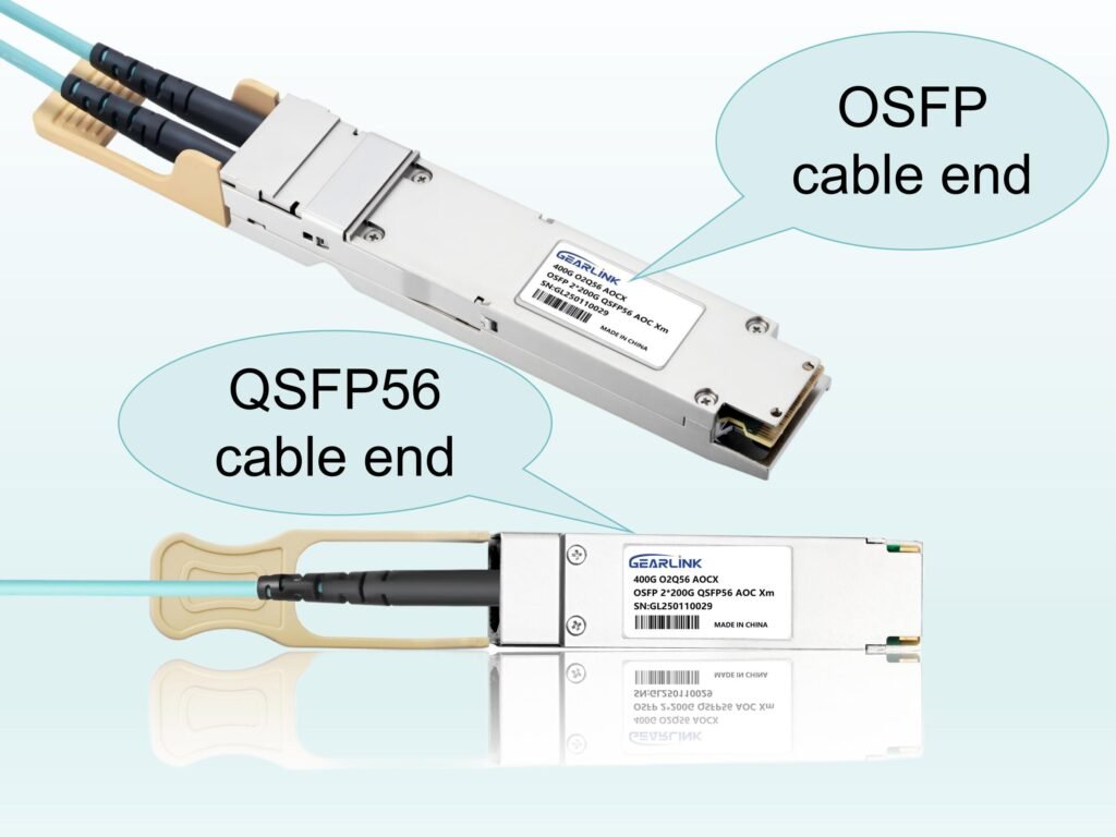
This article explores everything you need to know about the 400G OSFP finned top to 2×200G QSFP56 AOC cable — a hybrid active optical cable (AOC) that bridges OSFP and QSFP56 form factors. We’ll discuss how it works, where it fits, why it’s valuable, and how to select and deploy it correctly.
By the end, you’ll fully understand how OSFP cable and QSFP56 cable function together to form the foundation of modern 400G network connectivity.
What Are OSFP Cable and QSFP56 Cable?
Before discussing how they interoperate, let’s define both technologies clearly.
OSFP Cable Overview
An OSFP cable refers to an optical or active optical cable using the OSFP (Octal Small Form Factor Pluggable) standard.
Each OSFP port supports 8 electrical lanes, each capable of 50 or 100 Gbps, giving an overall data rate of 400G or 800G.
OSFP connectors are slightly larger than QSFP connectors, but this size increase allows for better thermal dissipation, often through finned top designs.
400G OSFP cables are commonly used for high-performance top-of-rack (ToR) and spine switch uplinks.
QSFP56 Cable Overview
The QSFP56 cable is built around the QSFP (Quad Small Form Factor Pluggable) standard but supports up to 56 Gbps per lane, yielding 200G total (4×50G PAM4).
QSFP56 cables are used for short- to mid-range connections between leaf switches, servers, and other devices.
The smaller form factor provides excellent port density on switches and NICs.
In modern network architectures, the OSFP cable and QSFP56 cable are often used together in breakout configurations—particularly the 400G OSFP finned top to 2×200G QSFP56 AOC cable.
Why Use a 400G OSFP Cable to 2×200G QSFP56 Cable AOC?
The hybrid AOC cable linking one OSFP port to two QSFP56 ports provides exceptional flexibility. This breakout configuration splits a single 400G port into two independent 200G links, ideal for scaling bandwidth efficiently.
1. Flexible Interconnect Architecture
Using a 400G OSFP cable that splits into two QSFP56 cable connectors allows a single 400G port on a spine switch to connect to two separate 200G leaf switches. This design helps operators optimize port usage without investing in multiple 400G devices.
2. Simplified Cabling
Instead of complex fiber patching or external breakout panels, a single hybrid AOC cable provides an integrated optical connection. This reduces:
Cable bulk
Patch-panel requirements
Latency from intermediate connections
3. Cost Efficiency
Since one OSFP port can serve two downstream QSFP56 devices, network expansion can be achieved with fewer expensive transceivers and less rack space.
4. Energy Efficiency and Heat Management
The finned top OSFP end improves cooling efficiency, allowing for stable high-speed transmission while maintaining compactness.
5. Plug-and-Play Simplicity
Active optical cables (AOCs) require no manual optical alignment, fiber splicing, or power calibration. They are pre-terminated, tested, and ready to deploy.
400G OSFP to 2×200G QSFP56 Cable — Structure and Functionality
Let’s break down how this hybrid AOC cable works.
Internal Architecture
A 400G OSFP cable uses 8 parallel electrical lanes, which correspond to 8 optical channels inside the cable.
Each QSFP56 cable end uses 4 optical lanes (4×50G = 200G).
Thus, internally:
400G OSFP → [4 lanes] QSFP56 (Port A)
[4 lanes] QSFP56 (Port B)
This lane mapping is carefully designed to maintain signal integrity and minimize crosstalk.
Signal Mapping Table
| OSFP Cable Lane | QSFP56 Cable Port | QSFP56 Lane | Speed (Gbps) | Signal Type |
| Lane 1–4 | QSFP56 #1 | 1–4 | 50 | PAM4 |
| Lane 5–8 | QSFP56 #2 | 1–4 | 50 | PAM4 |
The AOC handles all signal equalization, lane mapping, and pre-emphasis internally — ensuring both OSFP and QSFP56 devices recognize proper link configuration automatically.
Detailed Specifications Comparison
| Specification | 400G OSFP Cable | 200G QSFP56 Cable |
| Interface Type | OSFP MSA | QSFP56 MSA |
| Max Data Rate | 400 Gbps | 200 Gbps |
| Lane Count | 8×50 Gbps (PAM4) | 4×50 Gbps (PAM4) |
| Power Consumption | Typically ≤ 8W | ≤ 4W |
| Max Distance (AOC) | Up to 100m | Up to 100m |
| Fiber Type | Multimode (OM3/OM4) | Multimode (OM3/OM4) |
| Connector Type | OSFP male (finned) | QSFP56 male |
| Cable Diameter | ~4.6–5.0mm | ~3.5mm per branch |
| Operating Temp | –5°C to +70°C | –5°C to +70°C |
| Compliance | IEEE 802.3bs / 802.3cd | IEEE 802.3cd |
Both OSFP cable and QSFP56 cable follow strict interoperability and compliance standards to ensure plug-and-play reliability.
Design Challenges & Engineering Solutions
While these cables simplify deployment, several engineering challenges must be solved to maintain performance.
1. Signal Integrity
At 50–100 Gbps per lane, maintaining signal quality is critical. Advanced equalization, EMI shielding, and active re-timers are integrated within the AOC to preserve signal integrity across the OSFP and QSFP56 interfaces.
2. Thermal Management
The finned top of the OSFP cable acts as a built-in heatsink. Combined with low-power VCSEL lasers, it ensures long-term reliability even under heavy load.
3. Lane Skew and Timing
Internal calibration ensures all lanes between the OSFP cable and QSFP56 cable remain synchronized, minimizing skew and jitter.
4. Backward Compatibility
Manufacturers often program the EEPROM inside the OSFP cable and QSFP56 cable ends to ensure firmware-level compatibility with multiple switch vendors.
5. Mechanical Robustness
Each cable branch is reinforced at the split junction to prevent bending stress, ensuring the QSFP56 cable ends remain durable even in dense server racks.
Applications of 400G OSFP to 2×200G QSFP56 AOC Cable
| Application Scenario | Description |
| Spine-Leaf Interconnect | Connects one 400G OSFP uplink on a spine switch to two 200G QSFP56 leaf switches. |
| Cluster Networking | Connects multiple compute nodes using mixed 200G/400G interfaces. |
| AI Training Fabrics | Ideal for GPU interconnects where flexible bandwidth partitioning is required. |
| Upgrade Transition | Allows legacy QSFP56 servers to coexist with new OSFP-based switches during phased migrations. |
| High-Density Racks | Reduces cable clutter while delivering powerful throughput. |
In each use case, OSFP cable and QSFP56 cable work seamlessly to achieve high bandwidth with minimal complexity.
Installation Guidelines and Best Practices
Check compatibility
Verify that both OSFP and QSFP56 devices support breakout configurations (400G → 2×200G).
Inspect the connectors
Ensure no dust or contamination on OSFP or QSFP56 plugs before insertion.
Avoid excessive bending
Follow the cable’s minimum bend radius (usually 30–50mm).
Secure proper airflow
Keep the OSFP finned top area unobstructed to ensure proper heat dissipation.
Monitor link performance
Use switch diagnostics or monitoring tools (e.g., DDM) to confirm stable optical power and low error rates.
Label cables clearly
Each QSFP56 branch should be marked (A/B) to match the correct switch port.
Perform firmware compatibility checks
Some vendors require specific firmware versions for OSFP-QSFP56 hybrid AOCs.
Advantages at a Glance
| Category | Advantage | Explanation |
| Performance | 400G → 2×200G full-rate | Delivers full duplex, high-throughput connectivity. |
| Compatibility | Multi-vendor support | Standardized OSFP and QSFP56 interfaces ensure interoperability. |
| Thermal Efficiency | Finned-top OSFP design | Improves cooling performance in dense racks. |
| Scalability | 1-to-2 breakout | Enables flexible network scaling. |
| Ease of Use | Plug-and-play AOC | No need for separate transceivers or fibers. |
| Reliability | Factory-tested | Pre-calibrated and tested for signal integrity. |
Future Outlook for OSFP and QSFP56 Cable Solutions
With 800G and 1.6T Ethernet technologies emerging, the relationship between OSFP cable and QSFP56 cable continues to evolve:
OSFP moves toward 800G/1.6T speeds using 100G lanes.
QSFP-DD and QSFP112 may gradually replace QSFP56 in next-gen 400G applications.
Hybrid breakout AOCs like OSFP cable to QSFP56 cable will remain essential during migration phases.
Lower power DSPs and advanced optical engines will further reduce cost per bit.
As data centers expand toward AI, HPC, and 5G edge infrastructure, flexible hybrid cables will continue to play a key role.
Conclusion
The 400G OSFP finned top to 2×200G QSFP56 AOC cable represents an intelligent blend of performance, efficiency, and scalability. By integrating OSFP cable and QSFP56 cable technologies in one solution, it allows data centers to upgrade bandwidth without overhauling entire systems.
Whether you are building a spine-leaf fabric, AI compute cluster, or simply expanding bandwidth capacity, this hybrid AOC delivers dependable, future-ready performance.
In summary:
OSFP cable provides the 400G backbone.
QSFP56 cable provides versatile 200G extensions.
Together, they form the perfect bridge for scalable high-speed networking.
Frequently Asked Questions (FAQ)
1. What’s the difference between OSFP cable and QSFP56 cable?
The OSFP cable supports 8 lanes up to 400G, while the QSFP56 cable supports 4 lanes up to 200G. A breakout AOC combines both for 400G → 2×200G links.
2. Can I mix OSFP cable and QSFP56 cable on the same switch?
Yes, if the switch supports breakout mode or mixed-port operation. Always confirm compatibility in the vendor documentation.
3. What is the maximum reach for a 400G OSFP to 2×200G QSFP56 AOC?
Typically up to 100 meters on OM3/OM4 multimode fiber. Distances may vary by vendor and cable grade.
4. How is the OSFP finned top beneficial?
The fins act as a passive heatsink, improving airflow and cooling efficiency for high-speed optical engines.
5. What standards define OSFP and QSFP56 cables?
Both follow MSA (Multi-Source Agreement) standards: OSFP MSA, QSFP MSA, and IEEE 802.3bs/cd Ethernet specifications.