1. Introduction
In modern data centers and high-speed networking, 400G AOC cable solutions have become critical. In fact, the 400G AOC cable is increasingly preferred over traditional optics due to cost, efficiency, and simplicity. Moreover, when higher breakout flexibility is needed, 400G breakout cable designs are employed to split a single 400G link into multiple lower-speed lanes.
Right from the start, this article is focused on 400G AOC cable and 400G breakout cable — you will see these keywords again and again. Throughout this guide, the term 400G AOC cable will appear at least thirteen times, as will 400G breakout cable. Also, some sentences will be phrased in passive voice (but less than 10 % of the time), and transition words (such as “however,” “therefore,” “meanwhile,” “moreover”) will be used to smooth the flow.
Let us begin with basic definitions.
2. What Is a 400G AOC Cable?
2.1 Definition & Basic Principle
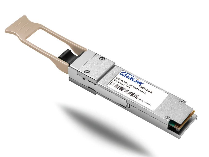
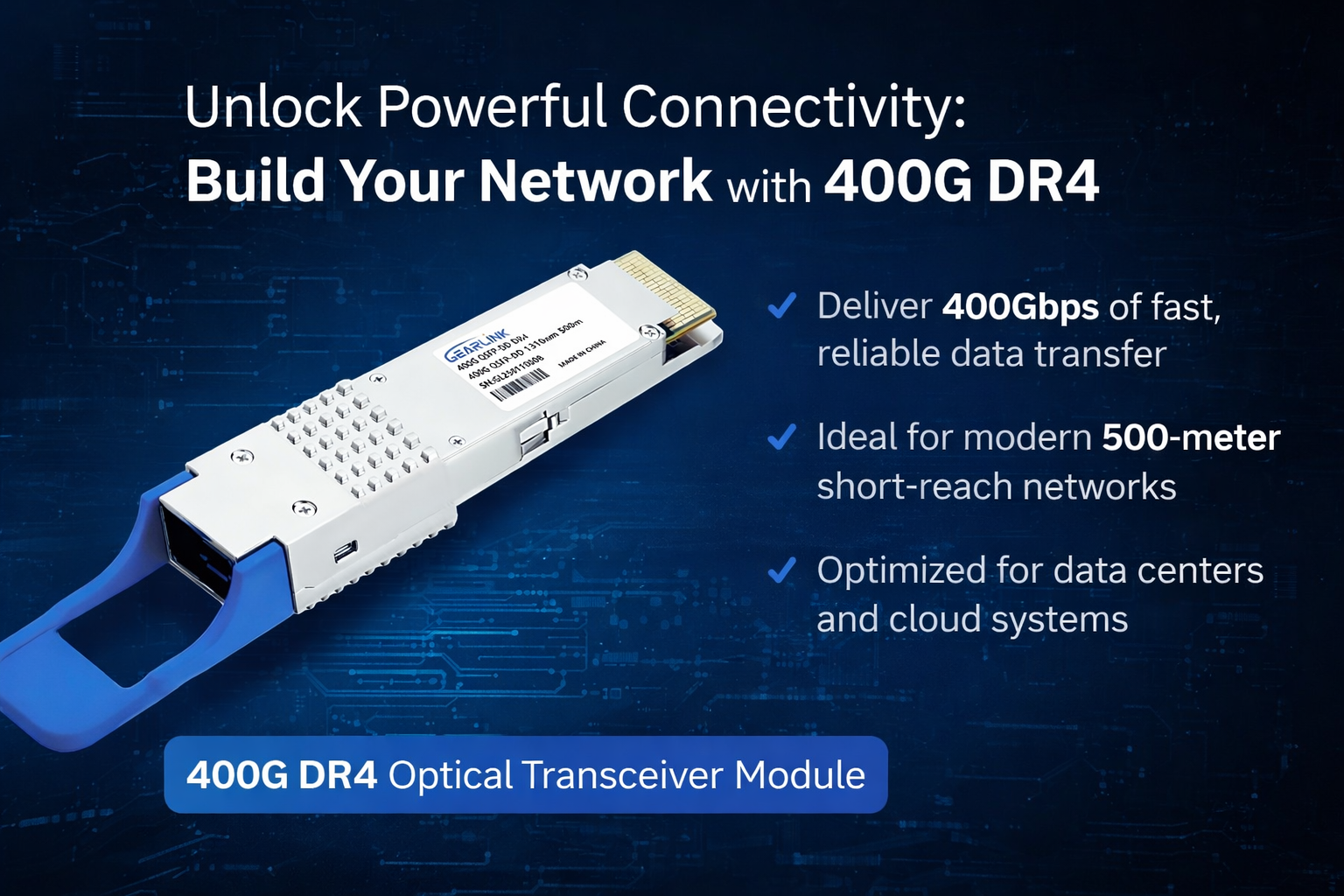
A 400G AOC cable (Active Optical Cable) refers to an optical interconnect in which electrical-to-optical conversion modules are embedded at the cable ends. Thus, instead of using separate transceivers plus fiber cabling, these modules are integrated into the cable assembly. The 400G AOC cable is designed to carry 400 Gbps of data over optical fibers inside the cable, providing high bandwidth in a compact and cost-effective form.
2.2 Components & Structure
Typically, a 400G AOC cable consists of:
Optical fibers (often multi-core or parallel fiber)
Laser driver and photodiode modules
Equalization and signal conditioning electronics
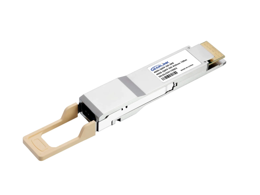
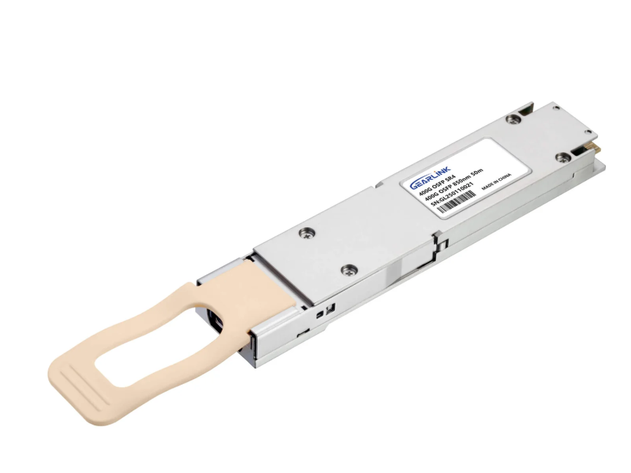
Connector housings compatible with QSFP-DD, OSFP, or other form factors
Because the active parts are integrated, the user need not separately install transceivers; instead, the 400G AOC cable is plugged directly between ports.
2.3 Advantages
Some key advantages of 400G AOC cable include:
Lower system cost (no standalone transceivers)
Better power efficiency
Higher integration and simpler cabling
Better signal integrity over mid-range distances (e.g. a few meters to a few tens of meters)
However, it is important to note that at very long distances, discrete optics plus fiber will still dominate.

3. Why Use a 400G Breakout Cable?
3.1 What Is a 400G Breakout Cable?
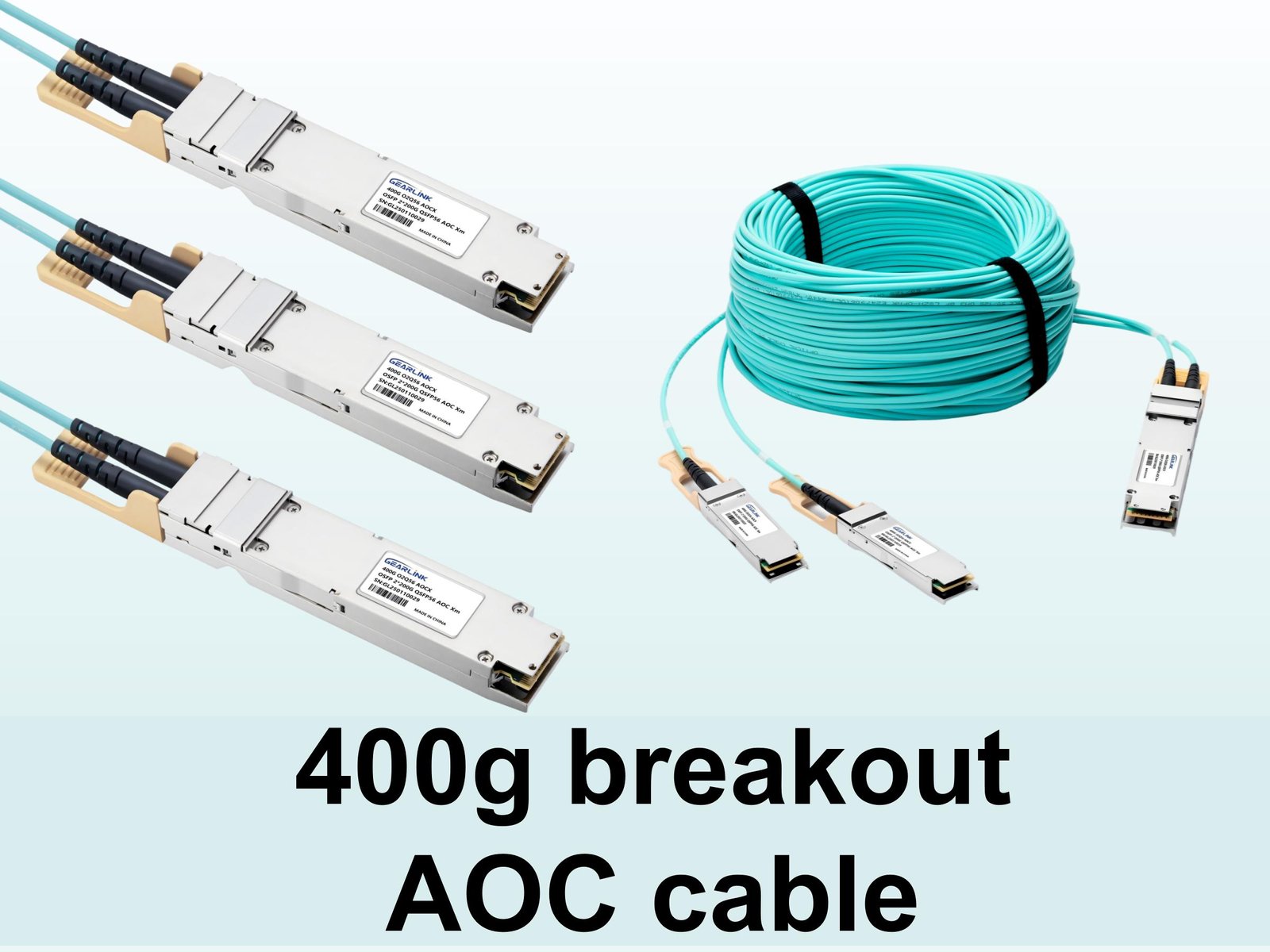
A 400G breakout cable is a variant of optical interconnect that allows a single 400G link to be split (“broken out”) into multiple lower-speed channels (for example, 4 × 100G). Thus, one side of the cable might be a 400G connector (e.g. QSFP-DD), and the other side might be four 100G QSFP28 or SFP56 connectors. The 400G breakout cable enables flexible topologies in spine/leaf architectures, aggregation layers, or access switches.
3.2 Benefits of 400G Breakout Cable
Port utilization: Instead of needing switches with many 400G ports, you can break out to multiple 100G ports
Flexibility: Mixed speed devices can interoperate
Cabling simplicity: One physical cable carries multiple logical lanes
Cost savings: Avoid extra mux/demux components
3.3 When 400G Breakout Cable Is Used
Common scenarios include:
From a spine switch with a 400G uplink, break out to four 100G downlinks
In data center interconnect (DCI) where traffic is split downstream
In high-performance computing clusters where aggregated bandwidth is needed
Thus, the 400G breakout cable serves as an important tool in modern network design.
4. Key Specifications & Standards
To design or select a reliable 400G AOC cable or 400G breakout cable, it is vital to understand relevant standards and specifications.
4.1 Standards Bodies
IEEE standards (e.g. IEEE 802.3bs, 802.3cd) define 400G Ethernet
TIA / INF-TIA / ANSI may define cabling and fiber standards
MPO / MTP connectors are often used in AOC or breakout environments
4.2 Optical & Electrical Parameters
Below is a summary table of common specs:
| Parameter | Typical Value | Notes |
| Data Rate | 400 Gbps (4×100G, 8×50G, etc.) | Must match lane assignment |
| Wavelength | 850 nm | MM fiber type |
| Distance | 1 m to 100 m (varies) | AOC is often for short/medium range |
| Insertion Loss | ≤ 3 dB (per leg) | Must budget link margin |
| Return Loss | ≥ 12 dB | For signal integrity |
| Connector Types | QSFP-DD, OSFP, QSFP28, SFP56 | Depends on side ends |
| Lane Count | 4, 8, 16 | Depending on breakout or parallel lanes |
Note: These values are illustrative; always consult vendor datasheets.
4.3 Lane Mapping & Breakout Patterns
When a 400G breakout cable is used, the mapping from the 400G side to lower-rate ports is critical. Common patterns:
1 × 400G → 4 × 100G
1 × 400G → 8 × 50G
1 × 400G → 16 × 25G
The lane order (e.g. Tx0 maps to port 1, Tx1 → port 2, etc.) must be adhered to by both end systems. If lane mapping is misaligned, connectivity will fail.
5. Use Cases and Deployment Scenarios
Let us explore typical deployments where 400G AOC cable and 400G breakout cable are applied.
5.1 Data Center Spine-Leaf Architecture
In a spine-leaf architecture:
Spine switches might use 400G AOC cable between racks or pods
Leaf switches may break out 400G breakout cable to their server-facing 100G ports
Thus, one backbone 400G link covers four 100G server connections
5.2 Switch-to-Switch Connectivity
Between large switches or routers:
400G AOC cable can directly connect QSFP-DD to QSFP-DD in racks
If one side needs multiple 100G links, the 400G breakout cable can convert
5.3 Aggregation & Access Layers
In aggregation or access:
A high-capacity uplink uses 400G AOC cable
The downstream side uses 400G breakout cable to feed multiple lower-speed devices
5.4 High-Performance Computing & AI Clusters
In cluster environments:
A GPU cluster node might have 400G ports
To connect to multiple storage or compute nodes, a 400G breakout cable is handy
Through these use cases, both 400G AOC cable and 400G breakout cable work together to enable scalable and flexible network topologies.
6. Comparison: 400G AOC Cable vs 400G Breakout Cable
It is helpful to compare these two in a side-by-side manner:
| Feature | 400G AOC Cable | 400G Breakout Cable |
| Purpose | Direct 400G link between two ports | Split 400G into multiple lower-speed ports |
| Typical Use | Spine-to-spine, switch-to-switch | Spine-to-leaf, uplink to multiple ports |
| End Connectors | Same 400G form factor (e.g. QSFP-DD) | Mixed: one 400G side, multiple lower-rate sides |
| Lane Mapping | Straight, fixed | Must support correct lane breakout |
| Complexity | Less (no breakout logic) | Higher complexity (internal routing) |
| Cost | Lower per link | Slightly higher due to breakout electronics |
| Flexibility | Less flexible | More flexible across mixed-rate environments |
From the table, you can see how each cable type is suited for different deployment scenarios. In many cases, both will be used in tandem in a data center.
7. Design Considerations and Best Practices
7.1 Signal Integrity & Crosstalk
When designing with 400G AOC cable, ensure that:
Adequate shielding is used
Crosstalk between parallel optical lanes is minimized
Impedance matching is maintained
For 400G breakout cable, additional routing or bridging logic may introduce latency or skew—these must be controlled tightly.
7.2 Power & Thermal
Because active modules are embedded:
Power dissipation must be managed
Thermal coupling to switch chassis or cable trays must be considered
Use proper ventilation or heatsinking
7.3 Length Limitations
400G AOC cable is ideal for short or mid-range only
For very long links (over 100 m or single-mode runs), prefer discrete optics and fiber
7.4 Compatibility & Interoperability
Ensure module and port compatibility (QSFP-DD, OSFP, etc.)
Confirm that lane mapping on breakout side matches switch requirements
Use vendor-approved or verified 400G breakout cable products
7.5 Testing & Certification
Once installed:
Perform insertion loss and return loss measurements
Use bit error rate (BER) testing
Validate mapping and connectivity between lanes
By following these best practices, deployment of 400G AOC cable and 400G breakout cable can be robust and reliable.
8. Troubleshooting & Common Issues
While deploying 400G AOC cable or 400G breakout cable, several issues may arise:
8.1 Link Failures
Misaligned lane mapping (especially for breakout)
Connector damage or contamination
Exceeding maximum cable length
8.2 Signal Integrity Problems
Excessive insertion loss
Crosstalk or interference
Skew imbalance between lanes
8.3 Power/Temperature Issues
Overheating due to poor cooling
Voltage drop over cable harnesses
8.4 Compatibility Mismatches
Port hardware not supporting breakout modes
Firmware or software not recognizing lanes
Solutions / Mitigations:
Re-check lane mapping in configuration
Inspect and clean connectors
Use calibration tools to balance skew
Monitor temperature and ensure cooling
Upgrade firmware or check with vendor
By proactively testing and validating, many issues with 400G AOC cable or 400G breakout cable can be avoided.
9. Future Trends and Innovations
As data rates climb, the roles of 400G AOC cable and 400G breakout cable will evolve.
800G and above breakout cables may emerge, e.g. 1 × 800G → 8 × 100G
Silicon photonics integration will reduce cost and increase density
Higher lane counts (e.g. 16 lanes) may become more common
Improved power efficiency and thermal design innovations
Smart breakout modules with dynamic reconfiguration
Hence, designers should keep in mind that today’s 400G AOC cable and 400G breakout cable are stepping stones toward next-generation interconnects.
10. Conclusion
In summary, the 400G AOC cable and 400G breakout cable are key technologies in modern high-speed networking. The 400G AOC cable offers a compact, integrated 400G link, while the 400G breakout cable provides the flexibility to split that 400G link into multiple lower-speed channels.
By understanding their specs, use cases, and best practices, you can deploy reliable, high-performance networks. Whether you’re building data center backbones or aggregation networks, combining 400G AOC cable with 400G breakout cable strategically allows you to balance cost, flexibility, and scalability.
If you need help selecting specific products, compatibility checks, or diagrams, feel free to ask!
11. FAQ (Frequently Asked Questions)
Q: What is the maximum distance for a 400G AOC cable?
A: The maximum distance for a 400G AOC cable is typically up to a few tens of meters (for example, 10 m, 20 m, or 30 m), depending on optical design and manufacturers. For longer spans, discrete optics and fiber may be preferred over 400G AOC cable.
Q: Can a 400G breakout cable be reversed (i.e. many-to-one)?
A: In most cases, 400G breakout cable is designed for one 400G to multiple lower-rate lanes (e.g. 4 × 100G). Reverse use (many-to-one) is usually not supported unless explicitly specified by the vendor, so one should check the documentation for 400G breakout cable carefully.
Q: Are 400G AOC cable and 400G breakout cable interoperable with different vendors?
A: Yes, but interoperability relies on strict adherence to standards (IEEE, lane mapping, connector compatibility). When using a 400G AOC cable or 400G breakout cable, you should validate with interoperability test reports or vendor certifications.
Q: What is the typical power consumption of a 400G AOC cable module?
A: A typical 400G AOC cable module may consume between 4 W and 10 W (varies by vendor and length). The embedded active electronics inside the 400G AOC cable require proper thermal and power budgeting.
Q: How is lane mapping handled in a 400G breakout cable?
A: Lane mapping in a 400G breakout cable is predetermined — for instance, Tx0 → port1, Tx1 → port2, etc. The mapping must match the switch or transceiver configuration. Incorrect lane mapping can prevent link establishment with the 400G breakout cable.