The relentless pace of digitalization and the explosion of compute-intensive applications, particularly in AI and machine learning, necessitate a continuous escalation of data center network speeds. Moving from 100 Gigabit Ethernet (100GbE) to 400 Gigabit Ethernet (400GbE) is no longer a luxury but a fundamental necessity for maintaining performance parity. In this critical transition, the choice of optical transceiver for short-reach, high-density links—the backbone of the data center—is paramount. A revolutionary contender in this space is the 400G-SR4 QSFP112 module. This new generation of optics leverages 100G per lane electrical signaling to deliver 400G throughput in the popular QSFP form factor. The central question for network architects is clear: Does the 400G-SR4 QSFP112 offer the optimal blend of technological advancement, compact size, and cost efficiency needed to power the next wave of data center buildouts? We will explore the technical evolution that birthed this module, analyze its distinct advantages over previous 400G iterations, and examine its strategic role in the migration to higher speeds.
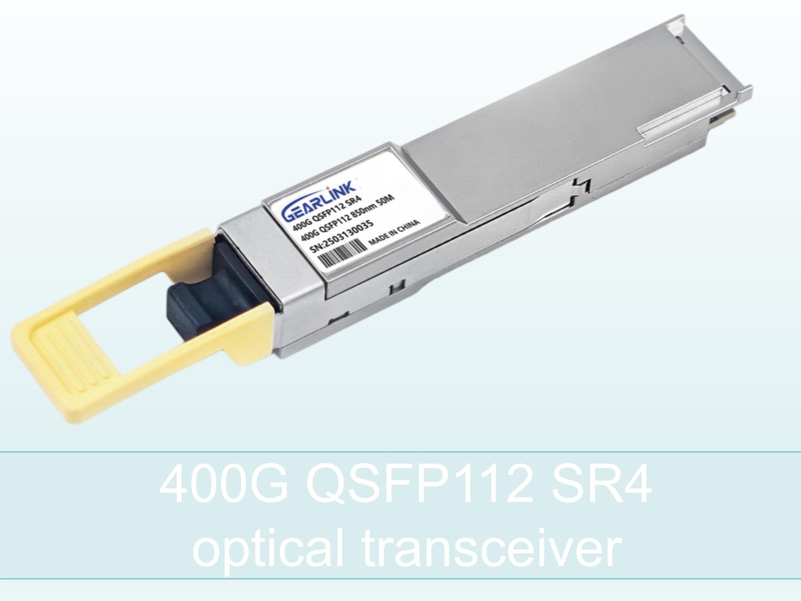
The Technical Leap: Understanding the 400G-SR4 QSFP112 Architecture
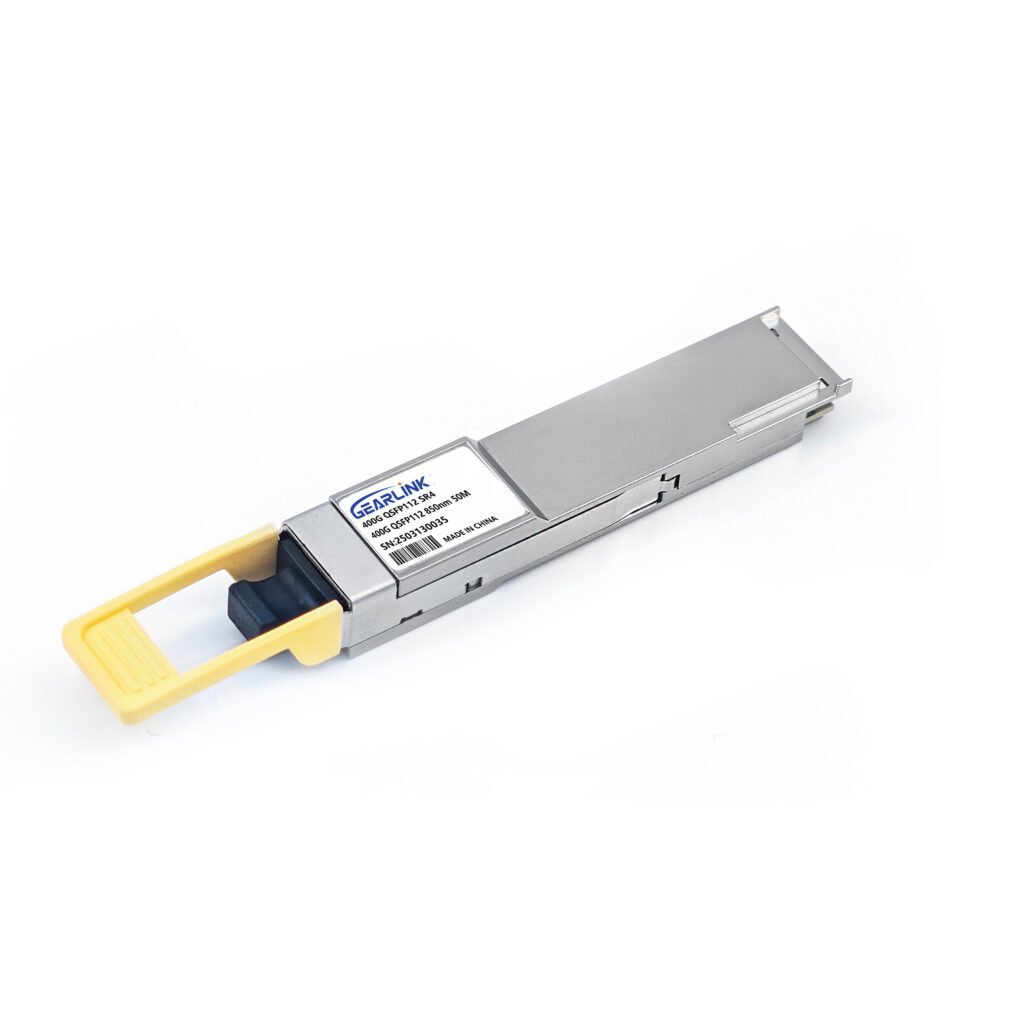
The 400G-SR4 QSFP112 represents a critical evolution in optical technology, shifting from the traditional 50G per lane PAM4 signaling found in earlier 400G modules to a cutting-edge 100G per lane approach.
The naming convention itself highlights this technical leap. “400G” denotes the total bandwidth, while “SR4” indicates the module uses Short Reach (SR) technology across four parallel optical lanes. The ‘QSFP112’ form factor is key; it is physically identical to the widely adopted QSFP-DD (Quad Small Form-factor Pluggable Double Density), but specifically engineered to support the new 100G/lane electrical signaling standard (112 Gbps raw data rate). This technological transition means that the 400G-SR4 QSFP112 achieves its 400G capacity using only four electrical lanes and four optical fibers, unlike its predecessor (400G-DR4/FR4/LR4) which typically needed eight electrical lanes running at 50G. This reduction in the number of required parallel lanes simplifies the complexity of the optical components and, crucially, reduces the power consumed per Gigabit. This increased efficiency and reduced complexity make the module a compelling choice for dense, power-sensitive environments.
Deployment Advantages: Density and Cost Efficiency
The 400G-SR4 QSFP112 offers significant practical advantages for data center deployment, primarily centered around maximizing port density and minimizing deployment costs.
Maximizing Port Density with QSFP112
Network operators strongly prefer the QSFP form factor due to its exceptional port density. Because the QSFP112 maintains the same physical size as the popular QSFP-DD, switches designed to accommodate high port counts (e.g., 32 ports in a 1U chassis) can seamlessly integrate these new modules. This seamless backward compatibility and familiar footprint simplify the hardware migration process considerably. By delivering 400G performance in a compact module, the 400G-SR4 QSFP112 allows data center fabrics to maximize bandwidth utilization per rack unit, a critical metric for hyperscale operators where every inch of space matters.
Optimized Cabling and Cost Structure
The SR4 designation means this module operates over Multi-Mode Fiber (MMF) and typically uses a 12-fiber MPO connector. Utilizing only four optical lanes (four transmit fibers and four receive fibers) for 400G means the module achieves high bandwidth without the exponential increase in fiber count often associated with parallel optics. For short-reach connections—the overwhelming majority of links within a data center—MMF remains the most cost-effective and easiest to manage cabling solution. Furthermore, the simplicity of the 100G/lane optical engine compared to more complex long-reach optics directly translates to lower manufacturing costs and, consequently, a more attractive purchase price for the end-user. This optimization of component cost and cabling infrastructure positions the 400G-SR4 QSFP112 as a cost-effective workhorse for campus and data center aggregation layers.
The Role of 400G-SR4 QSFP112 in AI Network Migration
")
400GBASE-DR4 QSFP112 PAM4 1310nm 500m DOM MPO-12/APC SMF Optical Transceiver Module
Price range: NT$669 through NT$799
400GBASE-FR4 QSFP112 PAM4 1310nm 2km DOM Duplex LC/UPC SMF Optical Transceiver Module
NT$750
The transition to 400G is largely being accelerated by the architectural demands of high-speed AI clusters, where latency and bandwidth are paramount. The 400G-SR4 QSFP112 plays a vital role in this specific application.
AI training relies on massive data movement between GPUs housed in adjacent racks, requiring ultra-low latency, short-distance links. The inherent design of the SR4 architecture, coupled with MMF, provides the low insertion loss and high reliability needed for these demanding connections. Moreover, the 400G-SR4 QSFP112 is fully compatible with breakout functionality. A single 400G port can be broken out into four individual 100G ports (using 4x100G MPO-to-LC breakout cables). This ability to connect a new 400G switch to existing 100G server Network Interface Cards (NICs) is crucial for phased network upgrades, allowing organizations to slowly and strategically increase the bandwidth of their server infrastructure without requiring a massive, simultaneous hardware overhaul. This flexibility ensures that the investment in new 400G switching capacity is utilized immediately, regardless of the legacy components still in use.
Longevity and Future-Proofing in the Optical Landscape
The decision to adopt the 400G-SR4 QSFP112 is also a choice that impacts the network’s future readiness for speeds beyond 400G.
The adoption of 100G per lane electrical signaling is not just a stepping stone; it is the foundational technology for the next generation of 800G and 1.6T optics. Modules operating at 800G will likely utilize 8x100G or 4x200G lanes, maintaining the same fundamental electrical interface. By deploying the 400G-SR4 QSFP112 today, network architects are essentially standardizing on the electrical signaling and thermal profiles that will define the next iteration of pluggable optics. Furthermore, the strong support from the QSFP Multi-Source Agreement (MSA) ensures that a competitive ecosystem of vendors will continue to produce compatible modules, guaranteeing supply stability and driving down long-term operational costs. This strategic choice secures the infrastructure for the demanding bandwidth requirements of future cloud and AI workloads.
Conclusion
The 400G-SR4 QSFP112 module is much more than a simple speed upgrade; it represents a convergence of high-performance technology (100G/lane) with the industry’s most preferred form factor (QSFP). By offering exceptional port density, superior power efficiency, and cost advantages through MMF usage, it addresses the core challenges facing data center expansion. Its immediate value in enabling cost-effective 400G deployment and its strategic importance as the foundation for future 800G speeds make the 400G-SR4 QSFP112 an undeniable key player in the ongoing evolution of high-speed networking.
Frequently Asked Questions (FAQ)
Q1: What is the main technical difference between 400G-SR4 QSFP112 and older 400G modules like 400G-DR4?
A: The main difference is the electrical signaling speed. 400G-SR4 QSFP112 uses 4 electrical lanes running at 100G each (for 400G total), while 400G-DR4 typically used 8 electrical lanes running at 50G each. This shift simplifies the optical engine.
Q2: Does the 400G-SR4 QSFP112 use Multi-Mode or Single-Mode Fiber?
A: The 400G-SR4 QSFP112 uses Multi-Mode Fiber (MMF). The ‘SR’ (Short Reach) designation indicates its optimization for short distances, typically up to 100 meters, which MMF handles cost-effectively.
Q3: Can the 400G-SR4 QSFP112 be used to connect to 100G switches?
A: Yes. Due to its SR4 architecture, it is ideal for breakout applications, where a single 400G port can be passively connected to four separate 100G ports using a specific MPO-to-LC breakout cable assembly.