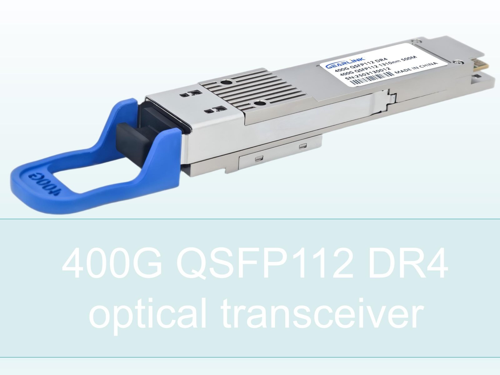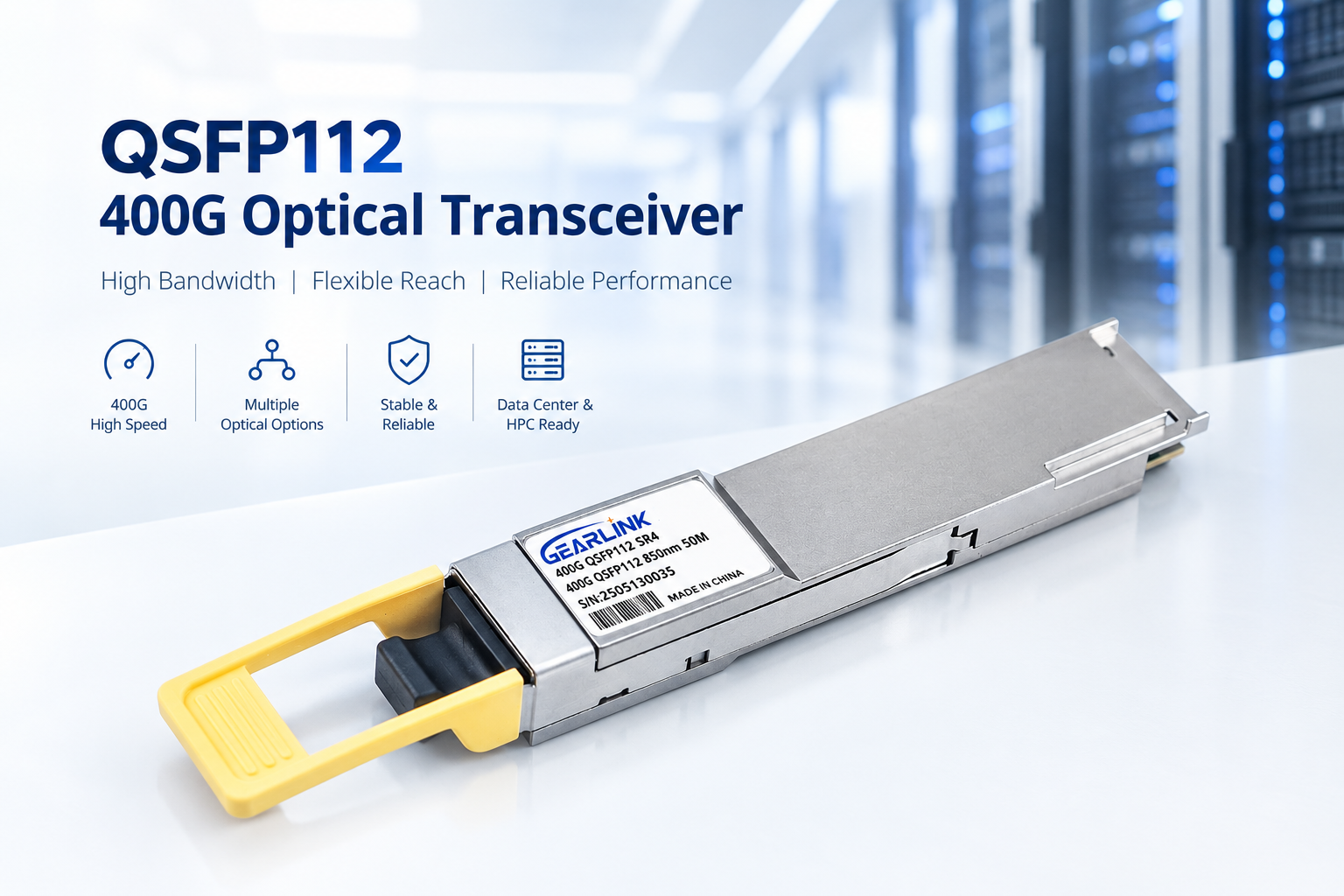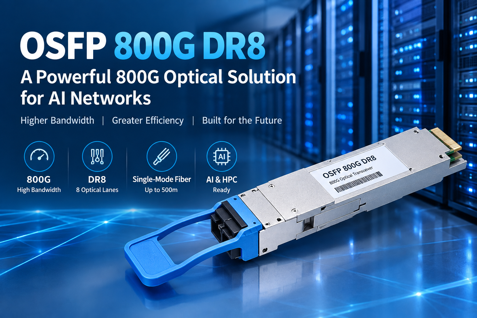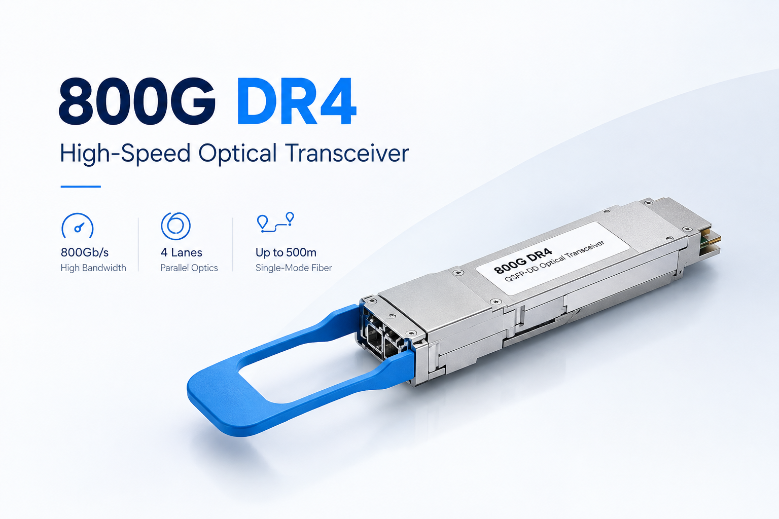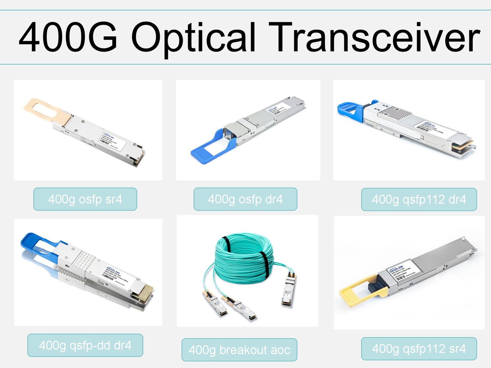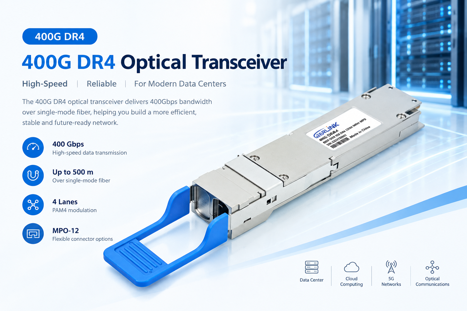
As cloud computing, artificial intelligence, and high-performance computing continue to grow, data centers need faster and more efficient network connections. 400G DR4 optical transceivers provide a practical solution for connecting switches, routers, and other high-speed network equipment over single-mode fiber. By combining four optical lanes with advanced PAM4 signaling, this technology supports 400G Ethernet connectivity while keeping fiber infrastructure relatively simple.
For network operators and system integrators, choosing the right optical transceiver is essential for achieving stable performance and controlling deployment costs. Therefore, understanding how 400G DR4 works, where it can be used, and how it compares with other 400G optical solutions can make network planning much easier.
In this guide, we explain the main specifications, working principles, applications, and selection considerations of 400G DR4 transceivers in straightforward terms.
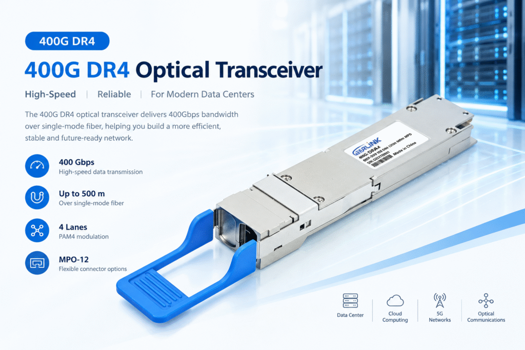
What Is 400G DR4?
A 400G DR4 optical transceiver is a high-speed optical module designed to transmit data at an aggregate rate of 400 gigabits per second. It typically uses four independent optical transmission lanes, with each lane operating at approximately 100 Gbps using PAM4 modulation.
The term DR4 describes the reach and lane configuration of the optical interface. DR generally refers to data-center applications using single-mode fiber over distances of up to approximately 500 meters, while the number 4 indicates four optical lanes.
Unlike traditional multimode optical solutions, 400G DR4 uses single-mode fiber, which supports high-speed transmission over longer distances than many common multimode configurations.
Key Specifications of 400G DR4
The following table summarizes the typical characteristics of a standard 400GBASE-DR4 implementation. Actual specifications should always be checked against the individual product datasheet.
| Parameter | Typical specification |
| Aggregate data rate | 400 Gbps |
| Optical lanes | 4 transmit and 4 receive |
| Per-lane optical rate | Approximately 100 Gbps |
| Modulation | PAM4 |
| Fiber type | Single-mode fiber (SMF) |
| Typical maximum reach | 500 meters |
| Optical wavelength | Around 1310 nm |
| Common connector | MPO-12, depending on the module |
| Common form factors | QSFP-DD and OSFP |
| Main applications | Data centers, cloud networks, high-speed switching |
These specifications make 400G DR4 suitable for high-density optical links within modern data centers. However, connector types, supported distances, and host compatibility can vary by product design.
How Does 400G DR4 Work?
To understand the advantages of 400G DR4, it helps to look at how data moves between two network devices.
First, an electrical signal from a switch or router is processed by the optical module. The module then converts the electrical data into optical signals. These signals travel through single-mode fiber to a receiving transceiver, where they are converted back into electrical signals for the destination device.
The transmission process uses four optical lanes in each direction. Each lane carries approximately 100 Gbps, allowing the module to achieve an aggregate bandwidth of 400 Gbps.
1. Four-Lane Optical Transmission
A standard DR4 optical interface uses four transmit lanes and four receive lanes. Each lane carries part of the total traffic, and the lanes work together to deliver the required bandwidth.
As a result, high data rates can be achieved without relying on a single optical lane operating at 400 Gbps.
2. PAM4 Modulation
PAM4 stands for four-level pulse-amplitude modulation. Unlike NRZ signaling, which uses two signal levels to represent data, PAM4 uses four levels.
This approach allows more information to be transmitted in each symbol. Consequently, PAM4 helps support higher data rates within the electrical and optical bandwidth limits of modern network hardware.
Nevertheless, PAM4 signaling requires careful signal-quality management. Transmitter performance, receiver sensitivity, fiber quality, and forward error correction can all affect link reliability.
3. Single-Mode Fiber Transmission
Single-mode fiber is designed to carry optical signals through a very small core. It helps reduce modal dispersion and supports higher-speed transmission over distances suitable for data-center interconnections.
For this reason, 400G DR4 is often selected when a network requires 400G bandwidth across single-mode fiber without moving to a more complex long-distance optical architecture.
Main Advantages of 400G DR4 Optical Transceivers
When network traffic increases, operators must balance bandwidth, equipment density, fiber availability, and operating costs. A 400G DR4 solution offers several practical benefits.
High Bandwidth for Modern Networks
First, 400G DR4 provides an aggregate data rate of 400 Gbps in a single optical module. This makes it suitable for high-capacity switch connections, aggregation layers, and data-center leaf-spine architectures.
In addition, 400G links can reduce the number of physical connections needed to deliver a given amount of bandwidth compared with lower-speed links, depending on the network design.
Efficient Use of Fiber Infrastructure
Another important advantage is its use of four optical lanes over single-mode fiber. With a suitable MPO-based cabling system, multiple optical paths can be managed through one compact connector interface.
Therefore, the design can simplify cabling compared with architectures that require many separate duplex connections. However, the actual fiber savings depend on connector polarity, patch-panel design, and the number of links deployed.
Flexible Network Design
400G DR4 is available in different module form factors, including QSFP-DD and OSFP implementations. These options allow network designers to select products that match their switch platforms and thermal requirements.
Furthermore, some compatible systems support breakout configurations, allowing one 400G port to serve multiple lower-speed connections. The supported breakout modes depend on the module, switch, firmware, and port configuration.
Suitable for High-Density Data Centers
Data centers often have limited rack space and power budgets. Higher-capacity optical links can help increase the bandwidth delivered by each switch port.
As a result, 400G DR4 can support network upgrades without requiring every connection to be built from multiple lower-speed modules. Power consumption and thermal performance should still be evaluated at the individual product and system level.
400G DR4 vs. Other 400G Optical Transceivers
Although several optical interfaces support 400G Ethernet, they differ in reach, fiber type, connector design, and deployment cost. Selecting the right interface depends on the distance between devices and the existing cabling infrastructure.
| Feature | 400G DR4 | 400G FR4 | 400G SR8 |
| Typical fiber type | Single-mode | Single-mode | Multimode |
| Typical reach | 500 m | 2 km | 100 m, depending on specification |
| Optical lane design | 4 lanes | 4 wavelength channels | 8 lanes |
| Typical wavelength | Around 1310 nm | Multiple wavelengths around the 1310 nm region | Around 850 nm |
| Common connector | MPO-12 | Duplex LC | MPO-based interface |
| Typical use | Data-center links | Longer data-center links | Short-reach data-center links |
Note: This comparison describes common implementations. Exact reach, connector, wavelength, and lane specifications depend on the applicable standard and product datasheet.
400G DR4 vs. 400G FR4
The main difference between these two interfaces is their transmission reach and optical architecture.
400G DR4 typically supports links up to 500 meters over single-mode fiber. By comparison, 400G FR4 commonly supports distances up to 2 kilometers and uses multiple optical wavelengths with wavelength multiplexing.
Therefore, DR4 is often a practical choice for shorter single-mode links, while FR4 may be more suitable when the connection must cover a longer distance.
However, FR4 and DR4 may use different connector types and cabling arrangements. Before purchasing either module, confirm the interface requirements of both connected devices.
400G DR4 vs. 400G SR8
The main difference is the fiber type and optical lane architecture.
400G SR8 is designed for short-reach transmission over multimode fiber, whereas DR4 uses single-mode fiber. SR8 may fit environments with existing multimode cabling, while DR4 can be more appropriate for single-mode fiber infrastructure.
Consequently, the better option depends on the installed fiber plant, link distance, port availability, and total deployment cost.
Where Is 400G DR4 Used?
The combination of high bandwidth and single-mode fiber makes 400G DR4 useful in several network environments.
Cloud Data Centers
Cloud service providers manage large volumes of traffic between servers, storage systems, and network switches. High-capacity optical links help support growing workloads and improve available network bandwidth.
In these environments, 400G DR4 can be deployed in switch-to-switch connections and other supported short-reach single-mode links.
AI and High-Performance Computing Networks
Artificial intelligence training and high-performance computing can generate substantial east-west traffic between servers and accelerators.
Accordingly, 400G optical connectivity can help support high-bandwidth network fabrics. The actual performance of an AI cluster also depends on switch architecture, network congestion, latency, and end-to-end configuration.
Enterprise and Telecommunications Networks
Large enterprises and telecommunications operators may use 400G links in aggregation networks, data-center interconnections, or high-capacity routing systems.
However, the module must match the specific equipment platform and optical interface. Compatibility should never be assumed solely because two products advertise the same data rate.
How to Choose the Right 400G DR4 Transceiver
Selecting an optical module involves more than checking its headline speed. To reduce installation problems, evaluate the following factors before placing an order.
1. Confirm Device Compatibility
Check the switch or router model, port type, supported form factor, and vendor compatibility requirements. Also verify whether the equipment requires a particular firmware version or approved module coding.
A compatible optical interface is essential for establishing a stable link.
2. Check Fiber and Connector Requirements
Confirm that the installation uses single-mode fiber and that the connector arrangement matches the transceiver. Many DR4 modules use MPO-12 interfaces, but connector details can vary.
Additionally, verify fiber polarity and cabling layout before installation. Incorrect polarity can prevent the optical link from coming up.
3. Evaluate the Link Distance
Although 400G DR4 commonly supports up to 500 meters, the actual link must remain within the specified optical budget.
Measure the fiber route and account for patch panels, connectors, and other sources of insertion loss. If the link exceeds the supported distance, consider a suitable alternative such as a compatible FR4 module.
4. Review Power and Thermal Requirements
High-speed optical modules generate heat and consume power. Before deployment, confirm the module’s power consumption, operating temperature range, and cooling requirements.
This is particularly important in densely populated switches and high-performance data-center racks.
5. Compare Product Quality and Support
Price matters, but it should not be the only purchasing factor. Review test reports, warranty terms, product traceability, and technical support arrangements.
For large projects, it is also useful to request a sample for compatibility testing before committing to a full deployment.
Installation and Troubleshooting Tips
Even a suitable optical module may fail to establish a link if the cabling or configuration is incorrect. Fortunately, a structured troubleshooting process can help identify common problems.
| Problem | Possible cause | Recommended action |
| Link remains down | Incorrect port configuration | Check port settings and supported speeds |
| No optical signal | Dirty connector or incorrect polarity | Inspect, clean, and verify the fiber path |
| Intermittent link | Fiber damage or excessive loss | Check insertion loss and inspect the cable |
| Module is not recognized | Compatibility or coding issue | Confirm platform support and module specifications |
| High module temperature | Insufficient airflow | Check switch ventilation and module operating limits |
| Link errors increase | Signal quality or configuration issue | Review optical diagnostics, FEC settings, and port counters |
First, inspect the physical connection and make sure the fiber is correctly seated. Next, review the device logs and optical diagnostics, where available. Finally, confirm that both ends use compatible interfaces and supported configurations.
When handling fiber connectors, use appropriate cleaning tools and never look directly into an active optical port.
The Future of 400G DR4 in High-Speed Networking
As data-center traffic continues to grow, network operators need optical solutions that balance capacity, reach, and deployment complexity. Although 800G technology is expanding in AI and cloud infrastructure, 400G remains important for many existing networks and phased upgrades.
For organizations moving from 100G or 200G infrastructure, 400G DR4 can provide a practical path toward higher port bandwidth. Moreover, its use of single-mode fiber can fit network designs that already rely on single-mode cabling.
The best upgrade strategy depends on projected traffic growth, switch capabilities, power limits, and the expected service life of the equipment. Therefore, network planners should compare both current requirements and future expansion plans before selecting a transceiver.
Conclusion
400G DR4 is a practical optical connectivity option for high-speed data-center networks that require 400 Gbps bandwidth over single-mode fiber. Its four-lane architecture, PAM4 signaling, and typical 500-meter reach make it suitable for many switch-to-switch and other short-reach network connections.
Nevertheless, the right module must match the equipment, connector system, fiber path, and optical budget. By checking these details before deployment, network operators can reduce compatibility risks and build a more reliable high-speed network.
When evaluating 400G DR4 transceivers, prioritize verified specifications, platform compatibility, product quality, and long-term technical support. These factors help ensure that the selected solution meets the real requirements of your network.