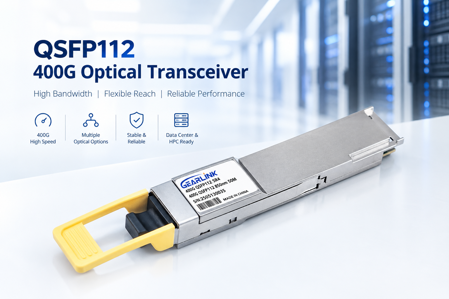
As data center traffic continues to grow, network operators need higher bandwidth without making their infrastructure unnecessarily complex. QSFP112 has emerged as an important 400G optical transceiver form factor for modern high-speed networks. By using four high-speed lanes and PAM4 modulation, it provides a practical way to support 400G Ethernet and other demanding data communication applications.
Compared with older 100G and 200G solutions, the architecture is designed for much higher aggregate bandwidth while maintaining a compact pluggable format. As a result, it can be used in switches, routers, data center interconnects, and high-performance computing environments.
However, choosing the right 400G module is not simply a matter of selecting the highest data rate. Fiber type, transmission distance, connector, optical design, FEC, power consumption, and host compatibility should also be considered.
This guide explains how QSFP112 works, where it is used, and how different 400G variants can fit different network requirements.
What Is QSFP112?
QSFP112 is a high-speed pluggable form factor designed around 112G-class electrical signaling per lane. In a typical 400G implementation, four electrical lanes are used, with each lane operating at approximately 106.25 Gbps using PAM4 signaling.
The four lanes work together to provide an aggregate throughput of approximately 400G. Some products specify an aggregate bit rate of around 425 Gbps because the physical signaling rate is higher than the nominal Ethernet payload rate.
The basic architecture can be summarized as follows:
| Parameter | Typical QSFP112 400G Design |
| Nominal data rate | 400G |
| Electrical lanes | 4 |
| Modulation | PAM4 |
| Lane rate | Around 106.25 Gbps |
| Optical lanes | 4 × 100G-class |
| Host interface | 400GAUI-4 |
| Form factor | QSFP112 |
| Power supply | Typically 3.3V |
| Management | CMIS-based |
| Applications | 400G Ethernet, data centers, HPC |
The exact specifications vary by optical type and manufacturer. Therefore, the host switch specification and the individual module datasheet should always be checked before deployment.
Why QSFP112 Matters for 400G Networks
Moving from 100G to 400G creates a significant increase in bandwidth. Nevertheless, network designers also need to control rack density, power consumption, cabling complexity, and equipment cost.
This is where the compact design becomes useful.
A 400G port can consolidate the bandwidth that would otherwise require several lower-speed connections. In a high-density switch, this can help simplify the front-panel layout while providing more bandwidth per port.
Moreover, the four-lane architecture makes several optical configurations possible. Short-distance connections can use multimode fiber, while longer links can use single-mode fiber and different wavelength technologies.
For example, 400G solutions are available in SR4, VR4, DR4, FR4, and LR4 configurations. These options allow network engineers to select a module according to the required reach rather than using one optical design for every application.
QSFP112 Optical Types Explained
Different optical variants are designed for different distances and fiber environments. Understanding these differences is essential when planning a 400G network.
QSFP112 VR4 and SR4 for Short-Distance Links
VR4 and SR4 are intended for short-distance data center connections.
They typically use 850 nm optical technology and multimode fiber. Depending on the implementation and fiber grade, reach can range from several tens of meters to around 100 meters.
For example, some current products specify approximately 30 meters over OM3 and 50 meters over OM4 for VR4. SR4 implementations can reach around 100 meters over OM4.
These modules are well suited to connections between switches, servers, and other equipment within the same data hall.
| Type | Fiber | Typical Wavelength | Typical Reach | Connector |
| VR4 | MMF | 850 nm | 30–50 m | MPO-12 |
| SR4 | MMF | 850 nm | Up to 100 m | MPO-12 |
| DR4 | SMF | 1310 nm | Up to 500 m | MPO-12 |
| FR4 | SMF | CWDM | Up to 2 km | Duplex LC |
| LR4 | SMF | CWDM | Up to 10 km | Duplex LC |
Actual reach should always be verified against the module datasheet, fiber type, link loss, and host FEC requirements.
QSFP112 DR4 for Data Center Interconnects
DR4 is one of the most common choices for 400G single-mode connections.
A typical 400G DR4 design uses four optical channels around the 1310 nm region. Each optical lane carries approximately 100G PAM4 traffic, while an MPO-12 connector is normally used for the parallel-fiber interface.
Many commercial DR4 products support a reach of approximately 500 meters over single-mode fiber. This makes them suitable for connections between racks, rows, or nearby data halls.
Another advantage is breakout capability. A 400G port can potentially be connected to four 100G ports when the switch and cabling architecture support this configuration.
Therefore, a DR4 module can be useful when a network needs both high-density 400G connectivity and flexible 4 × 100G migration options.
QSFP112 FR4 for 2 km Links
FR4 is designed for longer single-mode connections than typical DR4 deployments.
A common 400G FR4 architecture uses four CWDM wavelengths, such as 1271 nm, 1291 nm, 1311 nm, and 1331 nm. These wavelengths are multiplexed into a duplex LC interface.
Because four optical channels are combined onto two fibers, the cabling can be simpler than a parallel MPO-based single-mode design.
Many 400G FR4 modules support approximately 2 km over single-mode fiber. For instance, current product specifications commonly list four 100G PAM4 optical channels, duplex LC connectivity, and 2 km reach.
This makes the design attractive for data center interconnects where the distance is beyond typical multimode limits but does not require a 10 km solution.
QSFP112 LR4 for Extended Reach
When a network requires a longer optical path, LR4 can be considered.
A typical LR4 implementation also uses four CWDM wavelengths around the 1310 nm window. However, the optical budget and system design are optimized for longer transmission distances.
Commercial 400G LR4 products are commonly specified for distances up to approximately 10 km over single-mode fiber.
This type of module can be used for connections between geographically separated facilities, larger campus networks, and certain metro-scale data center applications.
However, longer reach does not automatically mean better performance. If a link only requires a few hundred meters, a shorter-reach solution may provide a more appropriate balance between optical budget, power, and cost.
QSFP112 and PAM4 Technology
One of the most important technologies behind 400G is PAM4.
Traditional NRZ signaling carries one bit per symbol. PAM4 uses four signal levels and can carry two bits per symbol. Therefore, higher data rates can be achieved without simply doubling the symbol rate.
For a 400G module, this approach allows four electrical lanes to operate at approximately 106.25 Gbps each.
The concept can be simplified as follows:
| Technology | Signal Levels | Bits per Symbol | Typical Use |
| NRZ | 2 | 1 | Older lower-speed links |
| PAM4 | 4 | 2 | 200G/400G/800G-class links |
However, PAM4 also introduces tighter signal-integrity requirements. The four signal levels are closer together, so transmitter quality, receiver sensitivity, PCB design, FEC, and channel loss become increasingly important.
Consequently, a 400G deployment should not be evaluated only by optical specifications. The complete electrical and optical link should be considered.
QSFP112 vs QSFP-DD for 400G
Both QSFP112 and QSFP-DD can be used for high-speed networking, but their electrical architectures are different.
A typical 400G QSFP112 implementation uses four 100G-class electrical lanes. QSFP-DD 400G implementations may use eight electrical lanes at lower per-lane rates.
This difference affects the host interface, switch port architecture, module ecosystem, and system design.
| Feature | QSFP112 | QSFP-DD 400G |
| Typical 400G lanes | 4 | 8 |
| Per-lane signaling | 112G-class | 56G-class |
| PAM4 | Yes | Yes |
| Nominal bandwidth | 400G | 400G |
| Form factor | QSFP112 | QSFP-DD |
| Main consideration | Higher per-lane speed | More electrical lanes |
Neither architecture should be selected in isolation. Instead, the optical module must match the switch port, firmware, electrical interface, and supported standards.
QSFP112 Compatibility and Deployment
Before purchasing a 400G module, compatibility should be checked at several levels.
First, verify the physical form factor. The module must fit the host switch or router.
Second, check the supported electrical interface. The host must support the appropriate 400G lane architecture and signaling rate.
Third, confirm the optical standard. A DR4 module should not be treated as interchangeable with an FR4 module simply because both are rated at 400G.
Finally, check software and management support. CMIS-based diagnostics can provide useful information such as temperature, voltage, optical power, and module status.
A practical compatibility checklist is shown below:
| Checkpoint | What to Verify |
| Host port | 400G port and supported form factor |
| Electrical interface | 400GAUI-4 or applicable interface |
| Optical standard | VR4, SR4, DR4, FR4, LR4, etc. |
| Fiber | MMF or SMF |
| Connector | MPO/MTP or LC |
| Reach | Actual required distance |
| FEC | Required host/module FEC mode |
| Management | CMIS and diagnostic support |
| Power | Maximum module power supported |
| Temperature | Operating environment |
This approach helps prevent compatibility problems during deployment.
QSFP112 in Modern Data Centers
Data centers are moving toward higher port speeds as AI workloads, cloud services, virtualization, and distributed storage generate more traffic.
As a result, 400G connectivity is becoming increasingly important in high-density network architectures.
A typical deployment may connect 400G switches to other switches through short-reach multimode modules or single-mode parallel modules. For longer connections, CWDM-based designs can be used.
Furthermore, the 400G port can support network migration strategies. For example, a 400G DR4 connection may be used directly for 400G traffic or configured for 4 × 100G breakout when the network architecture allows it.
This flexibility can be valuable during gradual network upgrades.
How to Choose the Right QSFP112 Module
The selection process can be simplified into five questions.
1. How far is the link?
For short links, VR4 or SR4 may be appropriate. For approximately 500 m, DR4 is commonly considered. For 2 km or 10 km links, FR4 or LR4 may be more suitable.
2. What type of fiber is installed?
Multimode fiber is commonly used with short-reach 850 nm modules. Single-mode fiber is generally used for longer distances.
3. Which connector is required?
Parallel optical modules normally use MPO/MTP connectors, while CWDM-based FR4 and LR4 modules commonly use duplex LC.
4. Does the switch support the module?
Check the switch manufacturer’s compatibility list, supported CMIS version, FEC requirements, and firmware behavior.
5. What is the actual network objective?
A 400G link inside one rack has very different requirements from a 2 km data center interconnect. Selecting the module according to the real network environment can avoid unnecessary cost and complexity.
Conclusion
QSFP112 provides a compact and flexible approach to 400G networking. With four high-speed PAM4 lanes, it can support a range of optical architectures, from short-distance multimode links to longer single-mode connections.
VR4 and SR4 are designed for short data center links, while DR4 provides a practical solution for 500 m-class single-mode connections. FR4 extends the reach to around 2 km with CWDM technology, and LR4 can support longer links of around 10 km.
Most importantly, the correct module should be selected according to the complete link design rather than data rate alone. Fiber type, distance, connector, FEC, power consumption, host compatibility, and management support all matter.
As 400G networks continue to expand, understanding these differences can help network operators build faster, denser, and more manageable optical infrastructures.
1. What is QSFP112?
QSFP112 is a high-speed 400G optical transceiver form factor that typically uses four 100G-class PAM4 lanes for high-bandwidth data center and Ethernet applications.
2. What is the difference between QSFP112 and QSFP-DD?
A typical 400G QSFP112 design uses four higher-speed electrical lanes, while 400G QSFP-DD commonly uses eight lower-speed electrical lanes. The host switch must support the corresponding architecture.
3. How far can a QSFP112 transceiver transmit?
The distance depends on the optical type. Typical implementations include short-reach VR4/SR4, 500 m-class DR4, 2 km FR4, and 10 km LR4 solutions.
4. What fiber does QSFP112 use?
Short-reach variants such as VR4 and SR4 generally use multimode fiber, while DR4, FR4, and LR4 typically use single-mode fiber.
5. Is QSFP112 suitable for 400G data center networks?
Yes. QSFP112 is specifically used in 400G Ethernet and data center applications, with different optical variants available for different link distances and cabling architectures.